Spaced Ambisonics
Performance, recording, calculation, programming by Stefan Kießling, 2021
Website tested with Safari 14 and Chrome 90 on macOS 11.2.2
Dieterich Buxtehude (1637–1707): Præludium in D, BuxWV 139
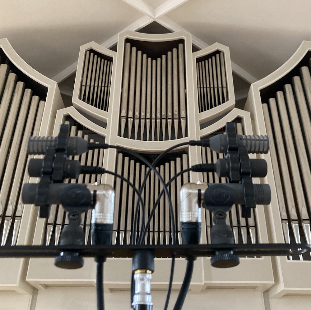 A MS (Mid-Side)-microphone setup creates, when properly mixed, two virtual microphones in an XY-configuration, that create a stereo sound (intensity stereo). Adding a second microphone for the mid-channel gives more flexibility in the pattern of the two virtual microphones. When turned by 90° to the right side, this setup will no longer capture sound for left and right side, but front-right and back-right instead. A second MMS-stack, turned by 90° to the left side, will provide the sound for front-left and back-left.
Here each MMS configuration consists of a Fig.8, an omni and a super-cardioid microphone.
Although this can be achieved with 3 microphones only - using a Double-MS-Setup - the setup described here adds time-of-arrival-stereo, which leads into a more spacious and natural sound, where as Double-MS is pure intensity stereo, that sounds somewhat flat.
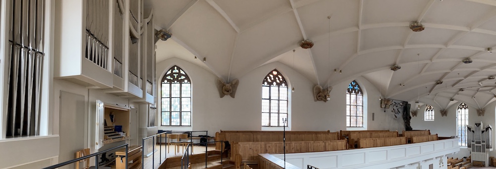
This recording here is made in the Stadtkirche Freudenstadt, Germany, which has two organs, placed at each end of one of the naves. The second (smaller) organ can be played remotely from the main organ's console. The interpretation makes use of both organs to create echo and dialogue effects.
This microphone setup is not only useful for surround sound. It also provides a lot of post-proc-flexibility for a stereo recording: if the room is reverberant the percentage of room sound can be adjusted.
You can adjust the mix of the microphones here while listening. Three possibilites:
- A pure time-of-arrival stereo capture, where you can adjust the reverberation.
- Stereo capture with a pair of fully flexible virtual microphones.
- Surround capture with two pairs of fully flexible virtual microphones.
Angle and pattern have an influence on how much room reverb is captured.
| Recording-Angle | |
| Polar Pattern | |
| Face back |
Some standard stereo setups can be quickly accessed here. K1 and K2 are two configurations that I personally enjoy.
As with the "Flexible Stereo" section, you can also set the stereo width and pattern of the virtual microphones here, independently for front and rear.
| Recording-Angle Front | |
| Polar Pattern Front |
| Recording-Angle Rear | |
| Polar Pattern Rear |
Resulting Mix
The calculator finds the appropriate mix by itself, having in mind the different sensitivities of the microphone models. The dB-values show the real gain, that is also influenced by the sensitivity. The percentage values display the logical participation of each microphone (as if the sensitivity of all mics would be the same).
| Front | |||
| Fig. 8 | |||
| Omni | |||
| Super Cardioid | |||
| Rear | |
Resulting Polarpatterns
Mixing those three microphones of each group results into a stereo sound that would be achieved with a pair of microphones of the angle and polar pattern shown here.
Resulting Stereo Image Front
(L and R are the loudspeakers. The little vertical lines represent a sound source coming from a certain angle. Their horizontal position reflects, where between the two speakers the human brain will think it comes from.)
360˚ Power sum Front
The polar graph shows the power sum for all directions. It describes how strong a sound from a specific direction is perceived. At 12o'clock is the front, 6o'clock is the back, 3 and 9 are the sides. The closer the curve is to the center, the softer the sound is in that direction. A perfect circle means: sound from all directions is captured with equal intensity.
Resulting Stereo Image Rear
The stereo image for the rear speakers can be different from the stereo image for the front speakers, as the rear speakers are usually placed with a wider angle.
360˚ Power sum Rear
To achieve a good separation between front and rear speakers the power sum graphs of front and rear should overlap as little as possible.
Equipment
Affiliate-Links