The „lungs“ of coincident stereo setups or: Coincident stereo setups in reverberant rooms.
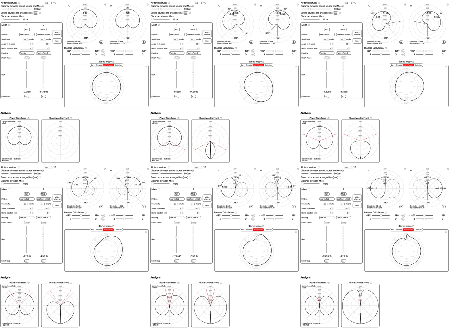
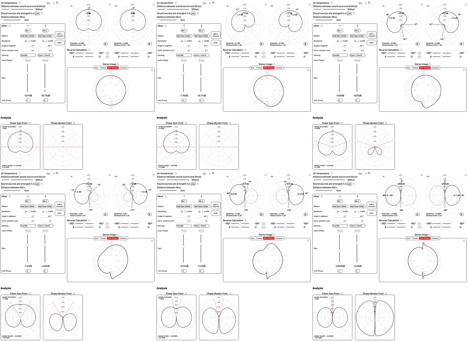
Product links are affiliate links. Some observations during my recording sessions motivated me to spend some time of further investigation. How stereo setups capture the „main characters“ is well understood and there are plenty of articles on that. Today a bit more focus on how they capture rear sound, which is important in reverberant rooms. I updated one of my calculators and designed a 360° Phase Monitor, that depicts, which sound - depending on its incidence angle - will be out of phase; so L and R will have opposite polarity, when played back through speakers. The graph show the level difference in decibels between L and R. If the graph moves towards the center, one signal is softer than the other, making the phase issue less noticeable. If the graph disappears, there's no phase problem.
For each figure there are two links. One leads to the setup in the polar patterns calculator, where you can adjust the settings by yourself and investigate the results. It features an abstract auraliser as well. The second link points to the setup in the Virtual Stage, where you can freely move around the mics and sound sources and listen to the result. Two sound source (noises) are put already in the rear of the stereo setup, as this article focuses on the capture of the ambience.
Deep link to this setup in the calculator
Deep link to this setup in the Virtual Stage
Deep link to this setup in the calculator
Deep link to this setup in the Virtual Stage
Deep link to this setup in the calculator
Deep link to this setup in the Virtual Stage

Its rear capture is mostly out of phase. Only when the recording angle is set very wide (=narrow stereo image), the out-of-phase-area is limited to the region, where the response of the whole setup is very small anyway. For smaller recording angles the out-of-phase-area is considerably larger and - what is really the worst - almost completely depicted in the center of the stereo image. I depicted that in the „stereo potato“, where the inner border marks the left, the outer border the right speaker and the position of the graph between the borders reflects the position of the phantom source between the loudspeakers. You can see, that all sounds out of the recording angle tend to move to the center between the speakers, and the more they are in the center, the more out of phase they are.
The conclusion is, that MS with C works best for very close miking in lesser to non-reverberant rooms. This might be surprising, as a cardioid is known for attentuaing rear sound. But that's obviously just a part of the game.
Deep link to this setup in the calculator
Deep link to this setup in the Virtual Stage

Deep link to this setup in the calculator
Deep link to this setup in the Virtual Stage
Deep link to this setup in the calculator
Deep link to this setup in the Virtual Stage
Deep link to this setup in the calculator
Deep link to this setup in the calculator.
To get the equalizing curve, use this tool: https://www.stefan-kiessling.com/?Thema=proximitydiffuse. Choose your mic. Click on „Equalizer…“ in the „Resulting Frequency Response“ and follow the instructions.
